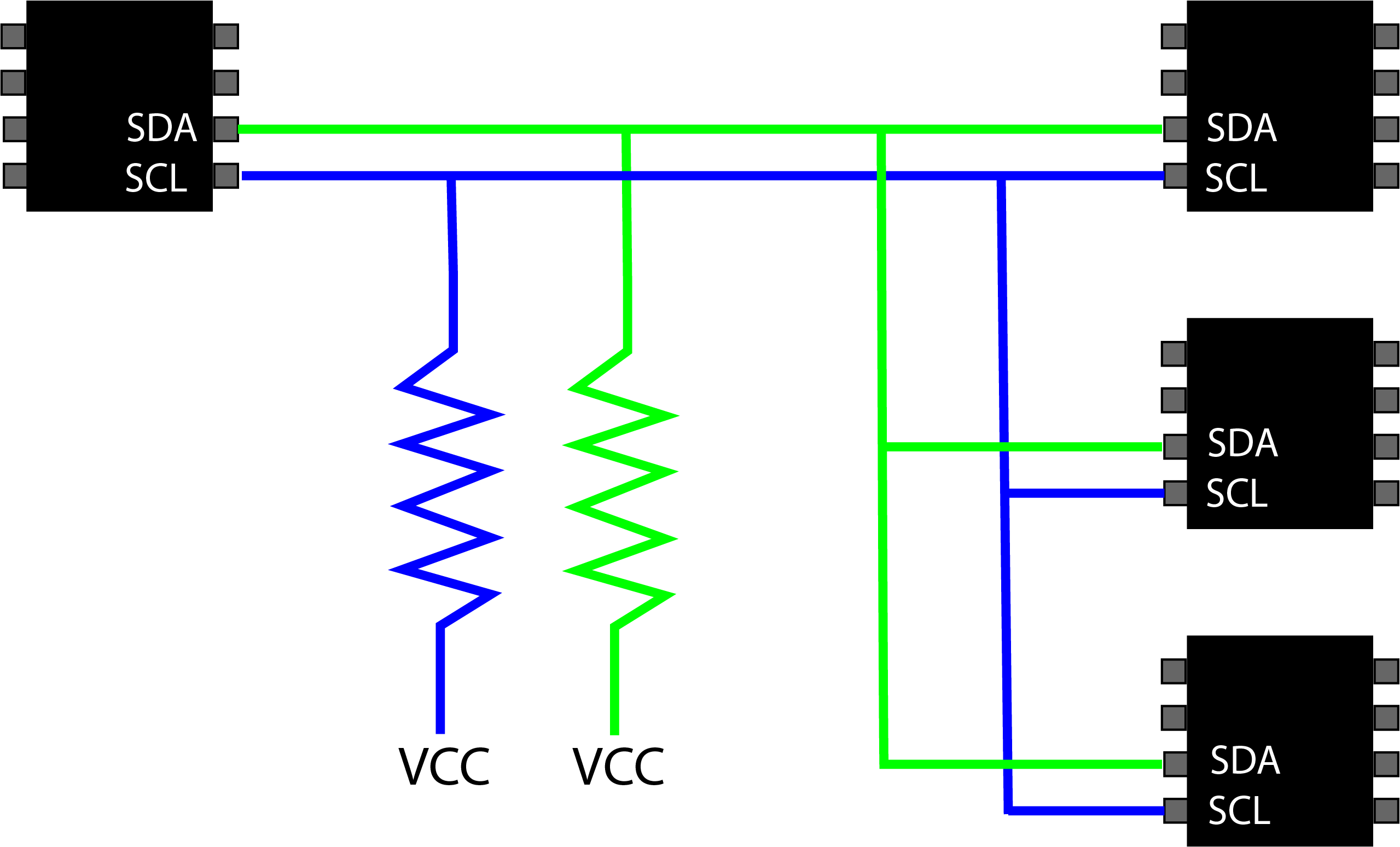
The ICs are connected to the I2C bus by two wires (SDA & SCL). The SDA and SCL lines must also be connected to Vcc using pull-up resistors. When an I2C device wants to send a signal, it will pull the line low by connecting it to the negative (or gnd) power rail. The resistor will limit the maximum amout of current to flow. A typical value of 4.7k should work for a bus speed of 100KHz.
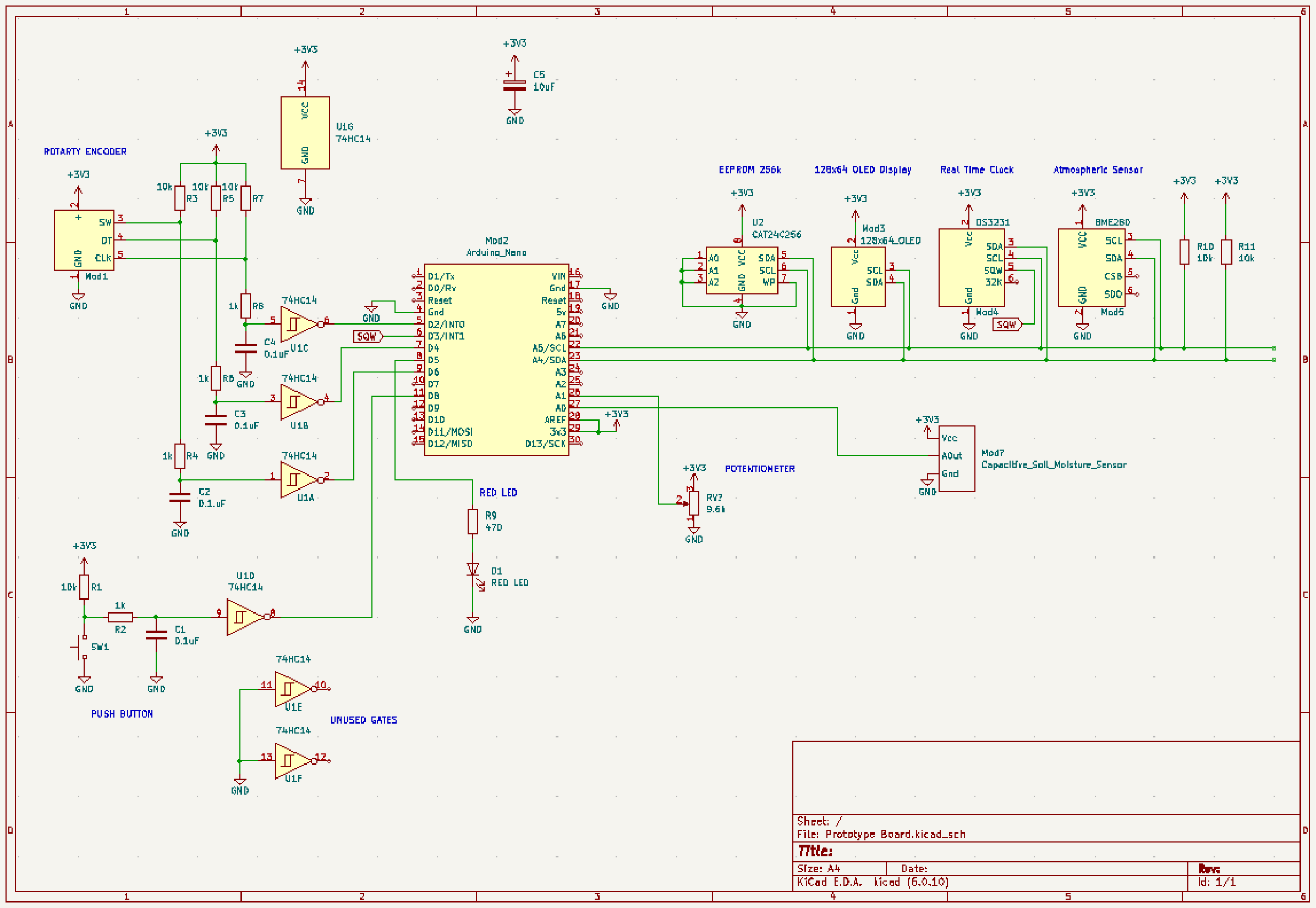
A prototype board was connected up to show the I2C interface. The schematic diagram of the prototype board can be seen below. In the schematic you can see that 4 modules were used for this example. Care must be taken when using modules since they may already have pull-up resistors already installed. If multiple modules are connected then the combined pull-up resistance must be calculated (or measured).
The pull-up resistance must be high enough to limit the maximum current when the I2C device pulls the SDA & SCL line low, but the resistance must be low enough to allow the signal to rise quickly enough for the bus speed. A simple rule of thumb is the fast the clock speed, the lower the resistance.
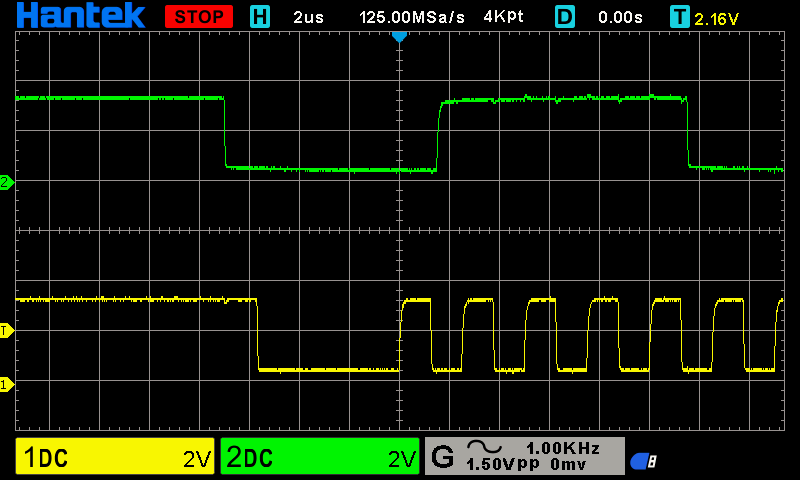
The capture below shows the SDA (green) and SCL (yellow) signals. The bus speed was 100KHz, Vcc was 3.3v and the pull-up resistance was about 2k ohms. The rising edge of the signal is acceptale.

Everything was kept the same as above, but the bus speed was increased to 400KHz. Looking at the SCL signal, the rising edge now has a visible slope. This slope can cause timing issues, making the I2C interface unreliable.

The image below shows the signals again, but this time the pull-up resistance was reduced to 700 ohms. The rising edge of the signals can be seen to be significantly faster. The only downside is the increase in power consumption. Just make sure not to lower the resistor such that the current could damage any of the I2C devices connected to the bus.
Example: The Arudino Nano has a maximum current of 20mA for each pin, so a pull-up resistor must be greater that 165 ohms assuming a Vcc = 3.3v. If another device on the bus has a lower maximum current then you must calculate the lowest resistance based on its current limitis.
In my example, the resistance was set to approx 700 ohm, this limited the current to about 5mA.
| Library Name | Author | Version |
|---|---|---|
| Adafruit BMP085 Library | Adafruit | 2.2.4 |
| Adafruit BMP280 Library | Adafruit | 2.6.8 |
| Adafruit BusIO Library | Adafruit | 1.15.0 |
| Adafruit GFX Library | Adafruit | 1.11.9 |
| Adafruit HMC5883 Unitied | Adafruit | 1.2.3 |
| Adafruit SSD1306 | Adafruit | 2.5.9 |
| Adafruit Unified Sensor | Adafruit | 1.1.14 |
| Dallas Temperature | Miles Burton, Time Newsome, Guil Barris, Rob Tillaart | 3.9.0 |
| GY521 | Rob Tillaart | 0.5.2 |
| OneWire | Jim Siudt, Tom Pollard, Robin James, Glenn Trewitt, Jason Dangle, Guillermo Lovato, et all. | 2.3.7 |
| QMC58883LCompass | MPrograms | 1.2.3 |
| RDV GY-512 Library | Gagan Singh | 1.0 |
| RTClib | Adafruit | 2.1.3 |