Using the ATTiny85 is not quite as easy and most of the Arduino modules since it does not have a USB interface. If we want to use the ATTiny series then we must use a ISP (In-circuit Serial Programmer). Fortunatly Arduino provides an example sketch which converts an Arduino module into an ISP. This page details all of the steps from start to finish to help yuo get started with this.
The istructions are specifically for the Arduino Nano, but will work for any Arduino Module.
The first thing to understand is the interface that will be used to program the ATTiny, this is the SPI (Serial Peripheral Interface). To connect up the SPI bus, we require three data lines.
These are connected SCK to SCK, MISO to MISO and MOSI to MOSI.
If we first take a look at the ATTiny85 pinout we can see these three pins.

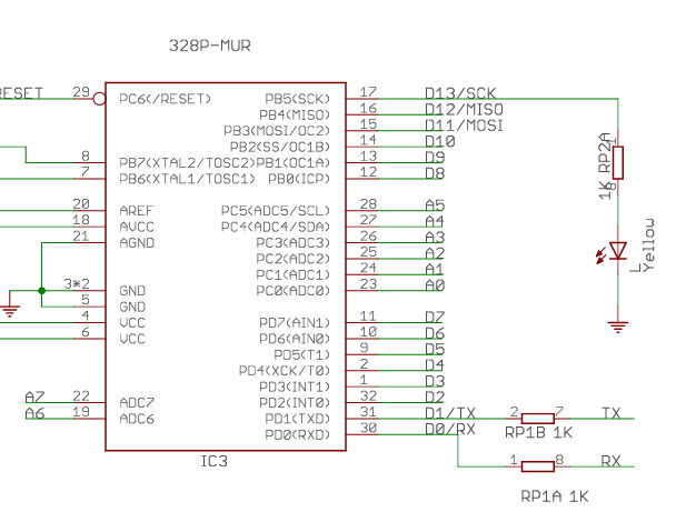
Finding the pins on the Arduino Nano took a little bit of looking. In the schematic for the Arduino Nano we can see SCK is on D13, MISO is on D12 and MOSI is on D11.
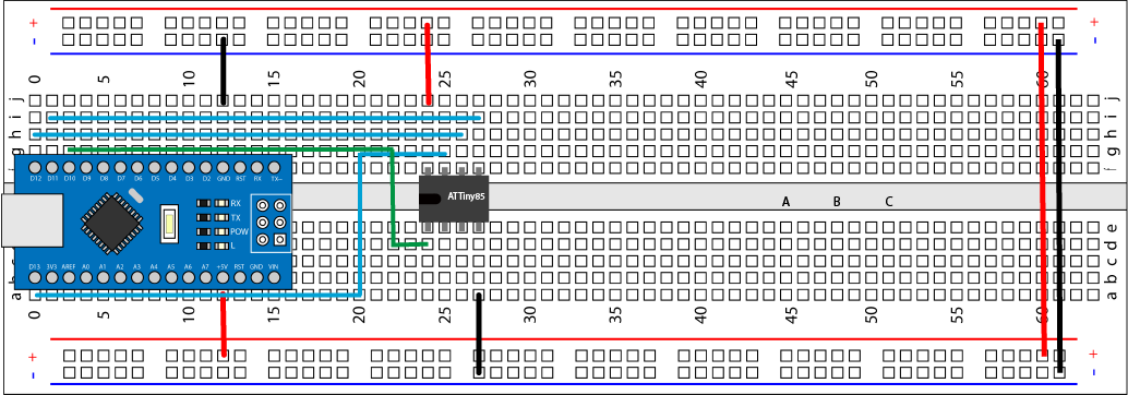
We now know most of the required connections (apart for Vcc and Gnd). The last connection is the RESET pin. This reset line must be set to allow the programming to occure. This can be any digital pin from the Arduino Nano. Below is an example of the connection layout on a prototype board, but it does not matter as long as you connect the 4 data lines, Vcc and ground. I have not shown the LED connections, but feel free to add them if you want.
Now we have all of the connection, we need to make the Arduino Nano into the ISP. This is simply done by opening the sketch from the installed examples. You will see 'ArduinoISP', upload this sketch as normal to the Arduino module you are going to use to program the ATTiny.
If we look at the default sketch, you can see it uses D10 for the reset pin, which we are going to use. It is possible to change this, If you look at the ArduinoISP sketch you will see the following lines. These are the default pins for the Reset line and three LEDs. The LEDs are optional, but do provide a little information.

After uploading the Arduino ISP sketch to the Arduino Nano, we need to add a 100 uF capacitor to the Reset pin on the Arduino module. This will prevent the Arduino from being reset, when we try to program the ATTiny. Connect the negative connection on the capacitor to the GND pin and the positive pin to the 'RESET' pin on the Arduino Nano. If you don't have a 100uF capacitor don't worry any value from 10uF and up should be OK, just make sure its rated for at least 5 volts
If you look at the image below, you can see the '-' sign with a white background from the top of the capacitor to the bottom, this points to the negative pin. Then there are two values 1000uF, this is the value of the capacitor. The larger the number the more power that the capacitor can hold. The second value is the voltage rating, in the image you can see this capacitor is rated for 16v. With capacitors it's only important to make sure this value is higher than the voltage you are going to use (5v).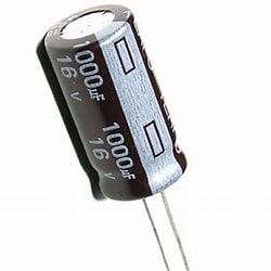
Now we have the connections made we need to take a look at the programming side. The first thing we must do is add the ATTiny boards to the Arduino development environment.
To do this me must tell the Arduino IDE where it can find the installation files. This can be done, by going to the 'File' menu and selecting 'Preferences'. When you select this you should see something like the window below displayed.
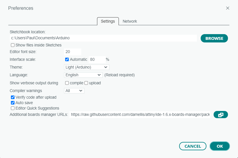
At the bottom of this window is 'Additional boards manager URLs'. At the end of this line is a button, click this and add the following URL:
https://raw.githubusercontent.com/damellis/attiny/ide-1.6.x-boards-manager/package_damellis_attiny_index.json
Note: You must CLOSE the Arudino envrionment and re-open it for this change to take effect.
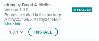
Go to the Board Manager (Tools - Board - Board Manager) and search for 'ATTiny' you should see the libraries to install. It should be something like the image below.
Now we can load a sketch on to the ATTiny85. Open the 'Blink' skectch from the installed examples. Before we load this into the ATTiny85 we must change the LED pin to 0, 1, 2, 3 or 4. Please take a look at the ATTiny85 pinout above. These numbers refer to PBx and you can then see the physical pin.
To upload the sketch to the ATTiny85.
To upload, go to the sketch menu and select 'Upload Using Programmer'