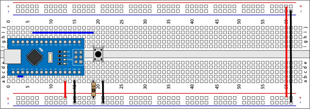
The need to debounce a switch comes as a suprise to many people. It normally occures when you hook up a switch to a microcontroller for the first time. The connection may look like the image below, or you might be using an internal pull-up resistor in the microcontroller.
The first bit of code turns a LED on while you are presssing the button and everything looks great.
Now you modify the program to toggle the LED on and off, when you press the button. This takes only a few minutes and you are then patting your-self on the back, thinking that was easy.
But then...
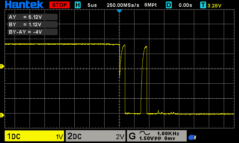
The LED does not toggel as expected, sometimes it works and sometimes it does not work. This is where new developers get stuck, trying to figure out what is happening. This problem is switch bouncing. The contacts of the switch may not make a solid connection for a few micro seconds after the switch has been pressed. This is not a switch problem, it's just a matter of physics. To fix this problem, we need to de-bounce the switch either electronically or in software. In the capture below, you can see several bounces during the first 10uS.
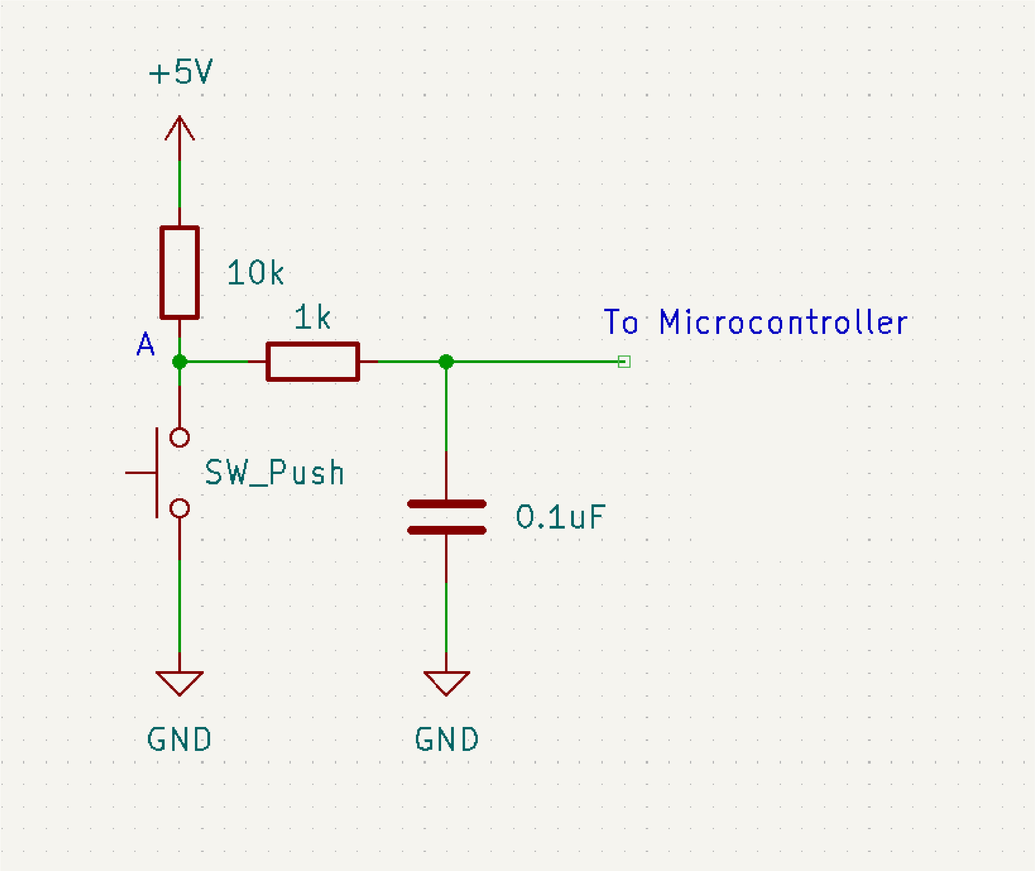
The first approach to de-bouncing a switch is to add a resistor and capacitor. This is basically a 1st Order low-pass filter, it's intended to block the high frequency components (or switch bounces). The schematic can be seen below, the value of the resistor and capacitor will need to be adjusted based on how much your switch bounces.
A typical layout on the prototype can be seen below.

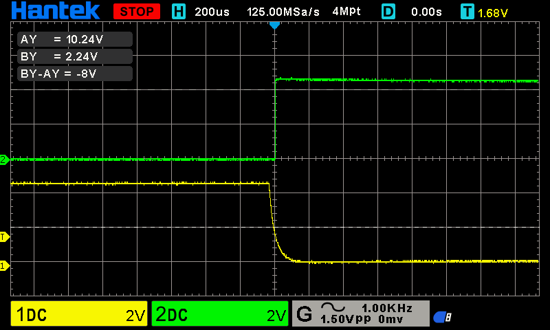
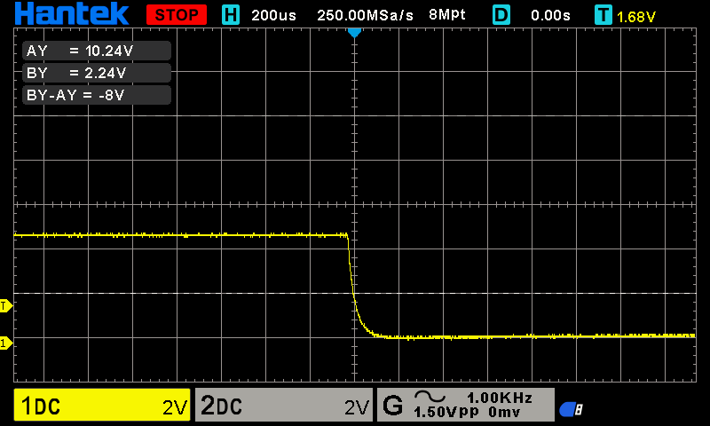
After the low-pass filter was added you can no longer see the bounces, but the falling edge now has a significant slope. This might be OK for your use case, but it's always best to avoid a slow rising or falling edge on a digital pin.
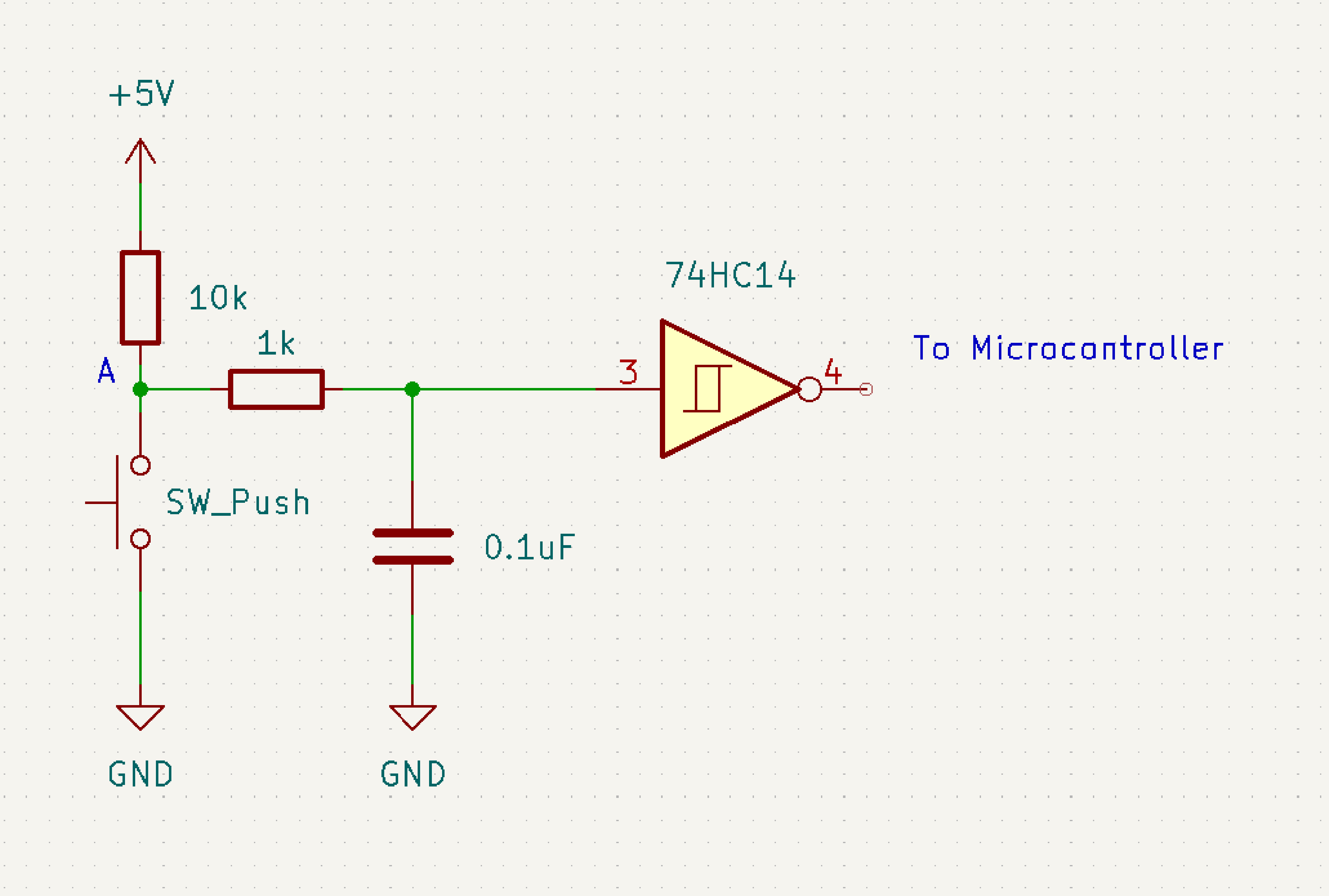
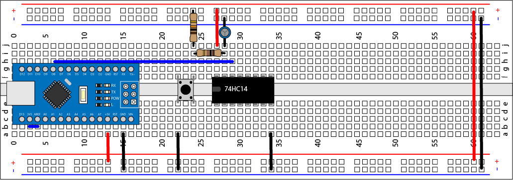
The slow rising and falling edge can be cleaned up by adding a schmitt trigger, after the low-pass filter. The schmitt trigger has two thresholds (Low and High). When the input signal reaches one of the triggers, the output is driven immediately high or low depending on threshold. A typical circuit can be seen below.
An example layout on a prototype board is shown below.
The image below shows both the signal before the schmitt trigger (yellow) and after (green). It can be seen that the falling slope is completly eliminated.
Note: The 74HC14 is a schmitt trigger, but it is also inverting. So a high input, results in a low output and a low input, results in a high output.