
Filters are a complex area for design, this page is just intended to introduce the topic. A lot of people getting started with electronics get confused with some of the basic concepts. I hope this helps explain some of these.
So, what does this mean.
Imaging we have three signal generators producing three different frequency sine waves (10Hz, 100KHz, 10MHz). If we connect these signals together, then we have a single signal but with three different frequency components.
- In the Time Domain, we only see a single signal. (Can be viewed using an Oscilloscope)
- In the Frequency Domain, we still actuall have three different signals... (Can be view using a Spectrum Analyzer)
A filter works in the frequency domain changing the signal levels, based on the signal frequencies
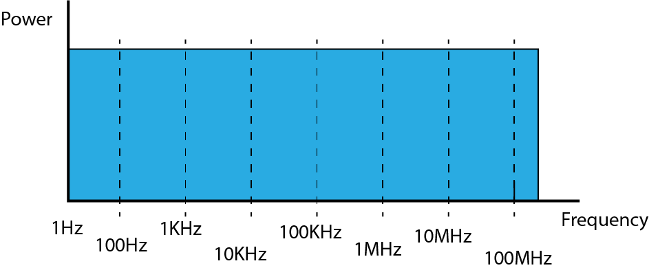
If we start by taking a look at white noise in the frequency domain in a perfect world you would see the following power/frequency distribution. The same power level is present for every frequency.
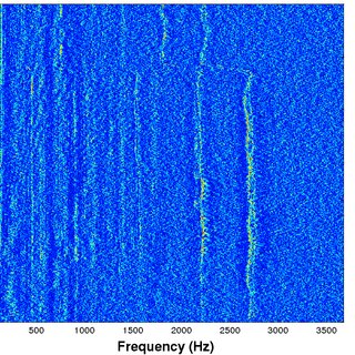
Just for interest, here's a picture of a sonar display, showing a frequency domain plot. Frequency is along the bottom, and the vertical axis is time. The color brightness indicates higher power for a specific frequency.
The vertial lines (~2200Hz & ~2700Hz)that you can see are actual boat propeller blades turning at different speeds. The brighter the line, the closer the boat is to the sensor.
Also if you follow the signal @ ~2700Hz upto the top of the image. It appears to change in frquency from 1800Hz to 2700Hz. This is the boat accelerating.
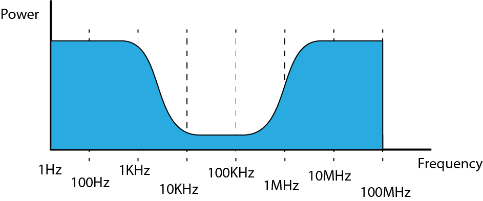
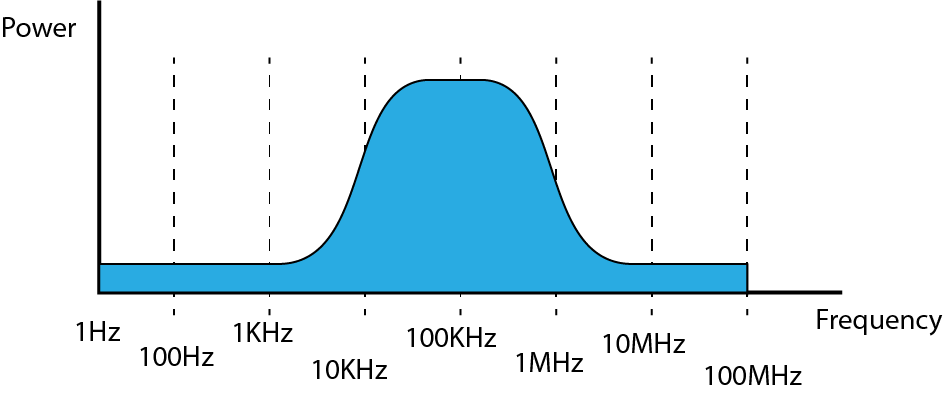
Now we know what white noise should look like in the frequency domain, we can now look at the filters to see how thay change the signal. There are actually two main 'types' of filters, the low pass and the high pass. Using two of the together create the other two type, the bandpass and the notch filer.
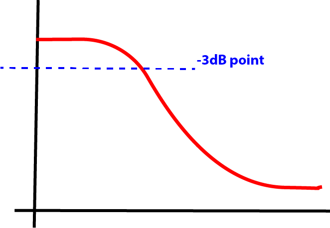
- A Low Pass Filter allows LOWER frequencies to PASS, but will attenuate (lower the signal power) frequencies above the cut off frequency.(Fc)
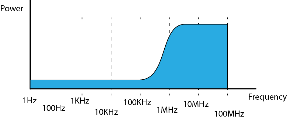
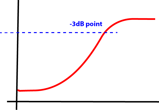
- A High Pass Filter allows HIGHER frequencies to PASS, but will attenuate (lower the signal power) frequencies below the cut off frequency.(Fc)
The diagrams below so ideal filter performance, in practice there will be a big difference...

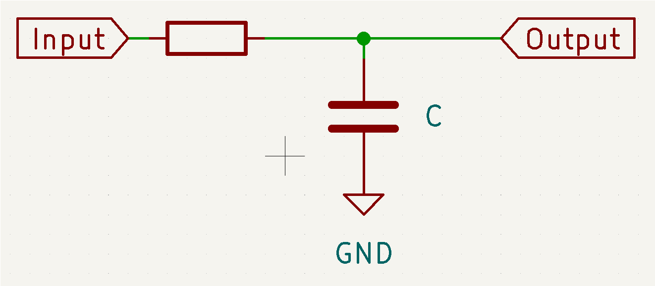
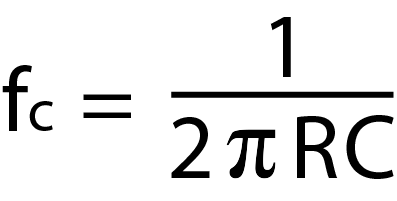
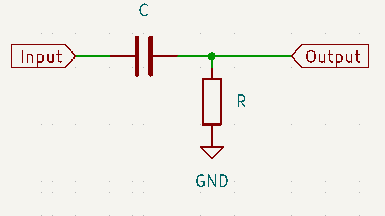
When a resistor and a capacitor are combined as shown in the circuit diagram, it acts as a simple filter. The formula calculates the '3dB' point. The is the frequency at which is input signal has been reduced by half.
When a resistor and a capacitor are combined as shown in the circuit diagram, it acts as a simple high pass filter. The formula calculates the '3dB' point. The is the frequency at which is input signal has been reduced by half.
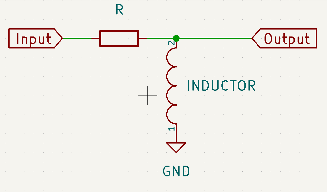
When a resistor and an inductor are combined as shown in the circuit diagram, it acts as a simple filter. The formula calculates the '3dB' point. The is the frequency at which is input signal has been reduced by half.
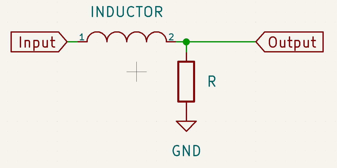
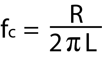
When a resistor and an inductor are combined as shown in the circuit diagram, it acts as a simple high pass filter. The formula calculates the '3dB' point. The is the frequency at which is input signal has been reduced by half.
The main issue is preventing the filter from distoring the signal you want and effectly reducing the signal you don't want.
The filters described on this page are very basic, but are still useful for many applications. Switch debouncing is a good example. Not only can it debounce the switch, but a fast rising or falling edge actually contains a very wide range of frequencies. These high frequency signal components can cause both audio and RF interference, this is the main reason digital components are generally kept isolated from the analog signals.
In case you want to do some more research, to convert from the time domain to frequency domain you perfrom a Fourier Transformation or normally FFT (Fast Fourier Transformation). I hated having to do these calculation when I was a student (we only had a pen and paper). It's a lot simpler today, infact I might make a simple frequency analyzer using the Arduino...