
Converting between serial data to parallel data can be performed with a dedicated SIPO chip (Serial Input, Parallel Output). The 74HC595 is an 8-bit SIPO IC, unsurprisingly it converts 8 serial bits data into 8 parallel bits. The task of converting serial to parallel data can be perform with a microcontroller, but this dedicated chip has it's uses. The most common use is to expand the output capabilites of a microcontroller.
If you wanted to drive a 7-segment display you typically need 8 output pins (7 for the number and 1 for the decimal place). If you want to drive 8 of these 7-segment displays would need 64 GPIO pins, most microcontrollers don't have this many available.
The SIPO (74HC595) provides a simple way of solving this problem. Serial data (SER) is clocked (SRCLK) into the IC and once the data is ready it can be latched into the output register (RCLK). This then sets the output registers with the data. As long as the output is enabled (OE), the data is then set on the output pins.
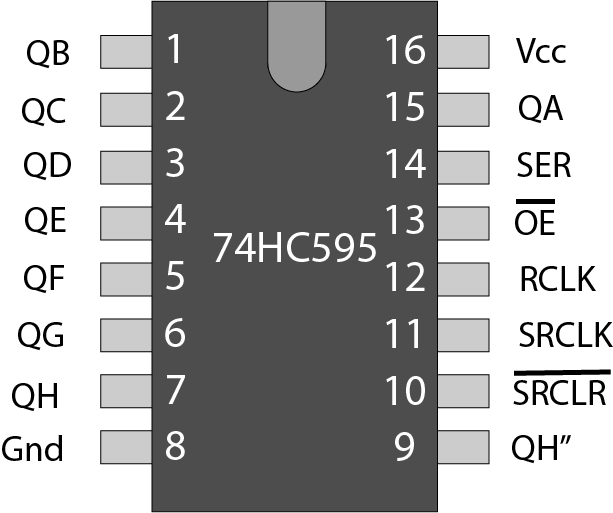
It is also possible to connect as many of these devices together. The 74HC595 has a QH'. This is the 'carry pin', if you connect this to the SER pin on the next IC you can have as many output pins as you need. Note: You will also need to connect all of the clock lines, but you don't need any extra pins from the microcontroller.
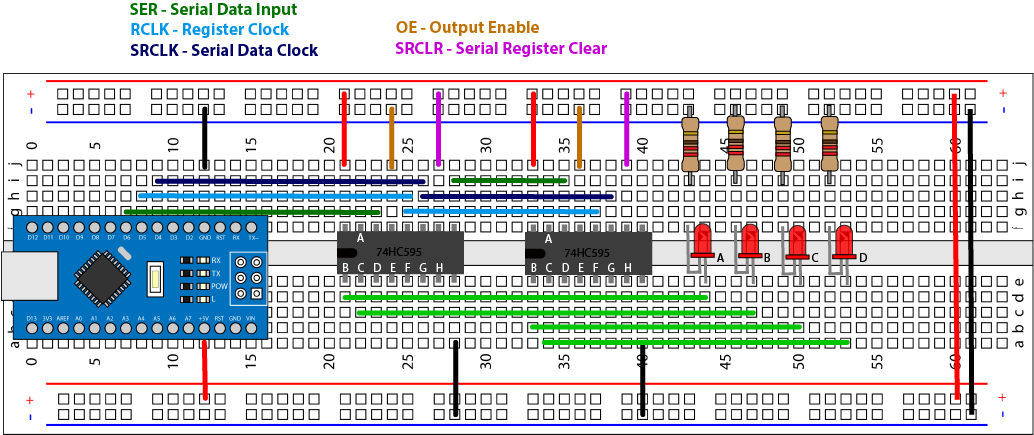
An example layout on a prototype board is shown below. I'm using D4, D5 and D6 to drive the 74HC595 IC. The chip is driven by rising edges, so pass data into the registers we need to do as follows:
Since in the example the OE is always enabled and the SRCLR is disabled the data will now be enabled on the output pins.
In this example only output B and C are used, so as long as xxxxx11x has been set LEDs A and B will light up. If we want to set all of the data we will need to drive the SRCLK line 16 times. Remember that each SRCLK pulse moves the data one bit to the right. So if we want the A output of the first chip to be set high, this will be the LAST data bit clocked into the registers.
Note: Since the OE and SRCLR lines are fixed, when power is first applied random data my be set on the output pins until your data is latched in. To prevent this you could use an extra GPIO pin to disable to OE signal until your data is set.
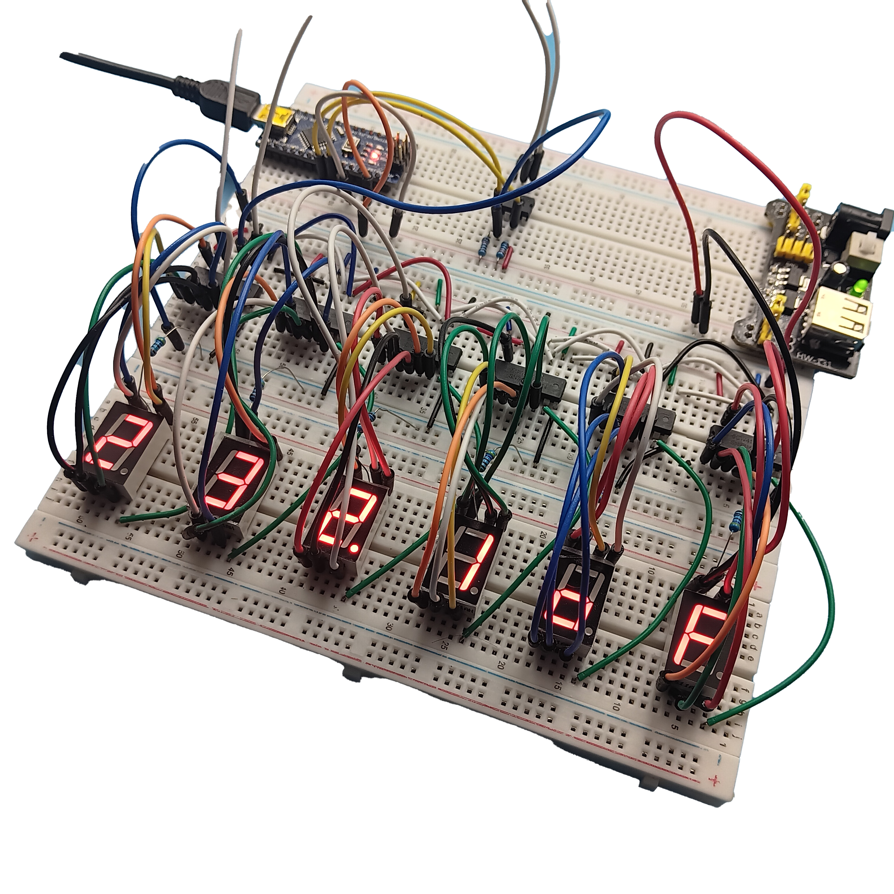
Its possible to connect many of these devices together. In my project to create an I2C driven 7-segment display I am using 6. I am building a complete module from start to finish including designing the PCB and fabrication process. I'm still working on this, so If you are interested please subscribe to my YouTube channel.
74HC595
The 74HC595 8-bit Shift Register datasheet.
Note: There are other manufacturers of these components, I have just included these datasheets for your reference.