This is the second part of my ATTiny development. The goal of this project is to make a custom 7-segment display controlled through the I2C interface. The development will be broken down into several parts to show how I evolved the design. The display module will be controlled by an ATTiny85 and this will then drive the 7-segment displays using the 74HC595 8-bit shift register.
If you would like to see the video, please feel free to click the link below, otherwise just read on.
Before getting started, If you want more information on how to use the 74HC595 or how to program the ATTiny85 then I have sections dedicated to these tasks.
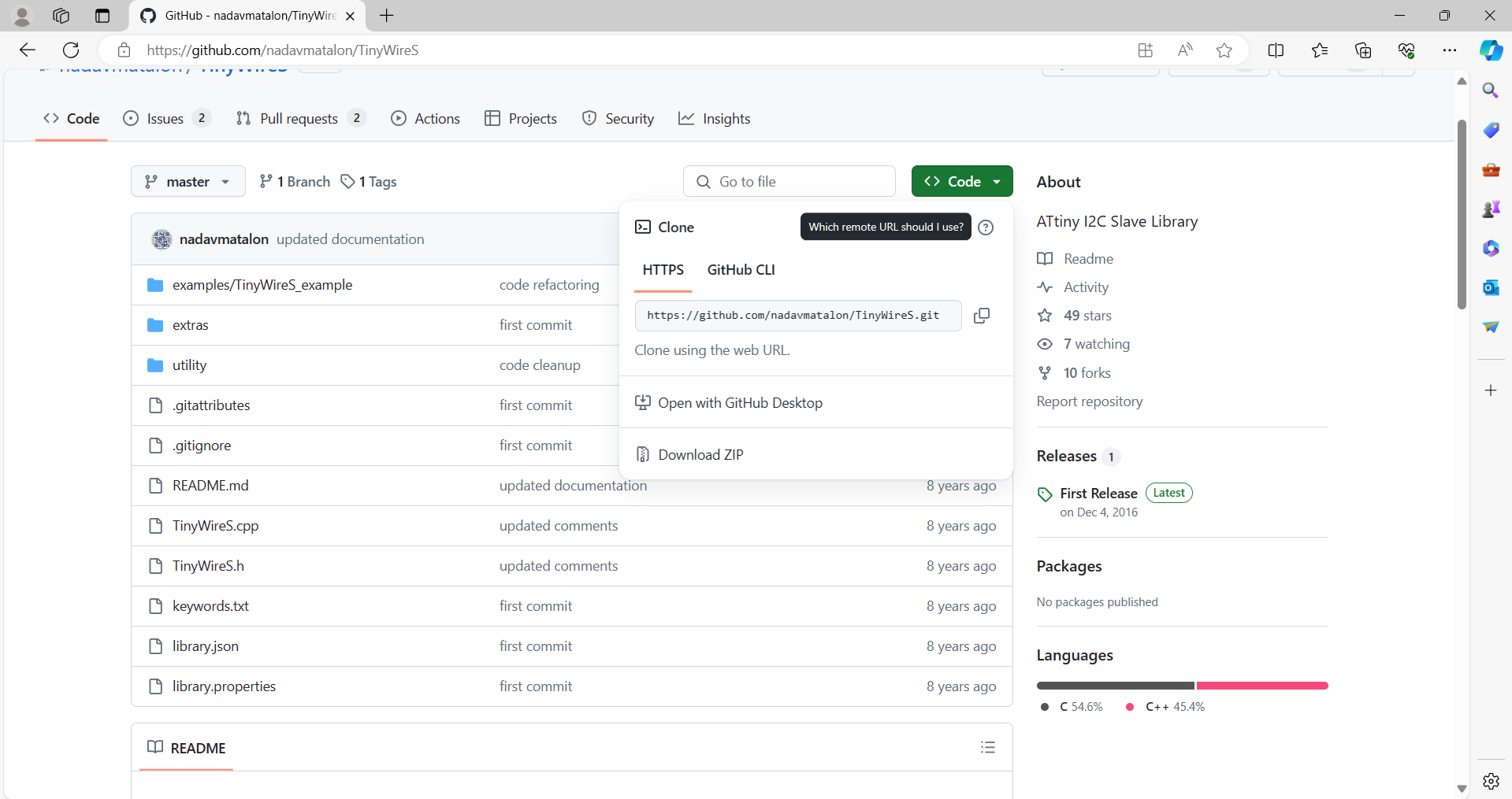
The first step in using the ATTiny as an I2C device is to download the libraries. The default Arduino libraries will not work with the ATTiny product line. There are a few libraries, but I chose to use the TinyWireS library. If you click on the link below, it will take you to the git hub repository where you can download the latest files or you can download files I am using from the bottom of this page.
If you are like me and don't know how to download the files from Github, On the git hub page, you should see a green button with "< > Code".If you click on this, a pull down menu will be displayed and at the bottom if an option to Download.zip file. Click this and the files will be downloaded.
After you have downloaded the files, unzip them and copy them into the Arduino library folder. You should find this under your 'Documents/Arduino/Library/ on your computer.
You are now ready to create a sketch for the ATTiny with I2C support.
If you look at the .ino file below you can see that its a very simple process, the TinyWireS library does all of the hard work. If you look in the setup section you will see that we just need to initialize it and set a ISR method which gets called when data is recieved on the I2C address. I am using the I2C address 0x04, but will be making this settable in the next step.
In the recieve section, all I do is take the bytes recieved and convert the data into serial data which I then clock on to the Shift-registers. Once all of the data has been processed I then clock the 'RCLK' line to latch the data onto the output.
// Please see credits and usage for usiTwiSlave and TinyWireS in the .h files of
// those libraries.

#include <avr/sleep.h>
#include <avr/wdt.h>
#include "TinyWireS.h"

uint8_t i2c_address = 0x04;

                    // Pin 1 - Reserved for Reset
uint8_t SER = 3;    // Pin 2 - SER to 74HC595
uint8_t SRCLK = 4;  // Pin 3 - SRCLK to 74HC595
                    // Pin 4 - Gnd
                    // Pin 5 - SDA
uint8_t RCLK = 1;   // Pin 6 - RCLK to 74HC595
                    // Pin 7 - SCL
                    // Pin 8 - Vcc

void setup()
{
  pinMode(SER,OUTPUT);                                  //Configure PB3 as output
  pinMode(RCLK,OUTPUT);                                 //Configure PB1 as output
  pinMode(SRCLK,OUTPUT);                                //Configure PB4 as output


  //Clear any junk data from the Shift Registers
  digitalWrite(SER, 0);                                 //Set SER line LOW
  digitalWrite(RCLK, 0);                                //Set RCLK line LOW
  digitalWrite(SRCLK, 0);                               //Set SRCLK line LOW

  for(int x = 0; x<(8*6);x++){                          // For each settable bit in the Shift-registers 8-bits * 6 ICs
    digitalWrite(SRCLK, 1);                             // Clock the Serial Clock line High
    digitalWrite(SRCLK, 0);                             // Clock the Serial Clock line Low
  }
  digitalWrite(RCLK, 1);                                // Pulse the RLCK to clear any junk data on the output pins.
  digitalWrite(RCLK, 0);

  TinyWireS.begin(i2c_address);                         // Initiazlize the I2C Slave mode
  TinyWireS.onReceive(receiveEvent);                    // Register the onReceive() callback function
}

void loop()
{
}

// Gets called when the ATtiny receives an i2c write slave request
// This routine runs from the usiTwiSlave interrupt service routine (ISR)
// so interrupts are disabled while it runs.
void receiveEvent(uint8_t num_bytes)
{
  uint8_t display_byte[16];
  uint8_t master_bytes = num_bytes;

  for (uint8_t i = 0; i < master_bytes; i++){           // Process each byte of data from the master
    display_byte[i] = TinyWireS.receive();
    for (uint8_t x = 0; x < 8; x++){                    //Loop for each bit within data byte
      digitalWrite(SER, bitRead(display_byte[i], x));   //Set the SER pin based on the bit of data
      digitalWrite(SRCLK, 1);                           //Set SRCLK High
      digitalWrite(SRCLK, 0);                           //Set SRCLK Low
    }
  }
  digitalWrite(RCLK, 1);                                // Pulse the RLCK to data on the output pins.
  digitalWrite(RCLK, 0);
}
Upload this sketch using the Arduino ISP programmer and then place the ATTiny85 into the development board
When using anything on the I2C bus, the very first test should be using the included I2C scanner sketch in the Arduino Examples (Under Wire). If this does not detect the device, you have a probelm and need to resolve it before moving on. If you watch my video, you will see me forget to connect the Gnd wire to the ATTiny85 and later on I missed a Vcc connection to the 74HC595 ICs.
Once you can detect the ATTiny85 as a device on the I2C bus, then you can try to communicate with the module.
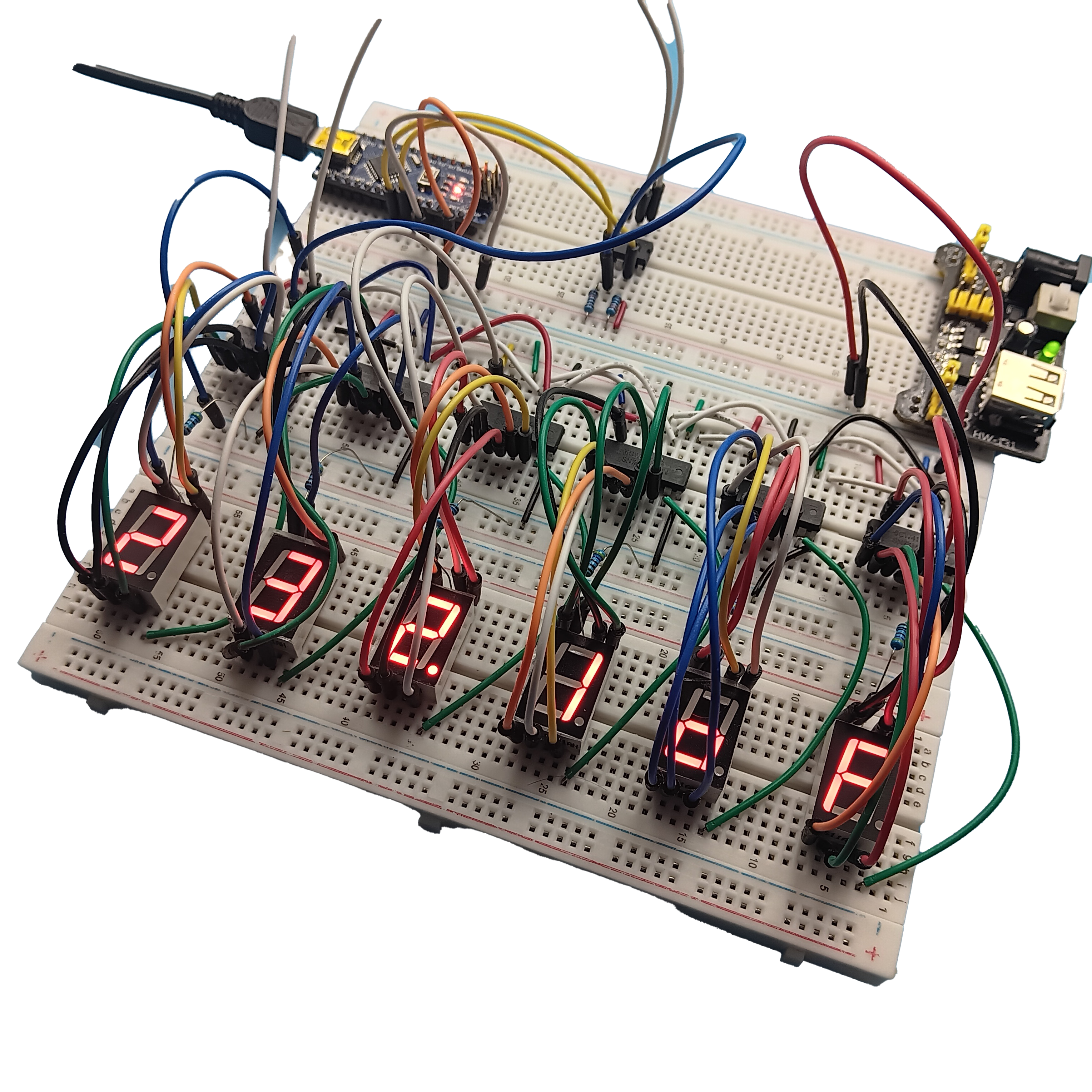
Below is a simple sketch that I used to test the display module. I started by sending 6 bytes with 0xff, this made sure that I was trying to turing on all of the outputs. If I had missed any connections then they would not light up and I could trouble-shoot. I then played with the bit sequence to confirm which bit set which segment on the display.
#include <Wire.h>
#include <Arduino.h>

uint8_t i2c_address = 0x04;

void setup() {
  Wire.begin();
  display("121212");
}

void loop() {
}


void display (String data){

Wire.beginTransmission(i2c_address);        //Start the I2C Session

 for (int x=data.length() ; x>=0 ; x--){    //Process the char array one byte at a time
   char aByte=data.charAt(x);
   char value = 0;
   char dp = 0;

   if ((x+1)//Check if we are setting the decimal place
    if (data.charAt(x+1) == '.'){
      dp = 0x01;
    }
   }

   switch (aByte){                          //Send the correct bit sequence for each char
      case '-':                             // '-' sign
        value = 0x04|dp;                    // Add the deciamal place if set
        Wire.write(value);                      //Send the encoded value to the display
        break

      case '0':                             // '0'
        value = 0xfa|dp;                    // Add the deciamal place if set
        Wire.write(value);                      //Send the encoded value to the display
        break

      case '1':                             // '1'
        value = 0x60|dp;                    // Add the deciamal place if set
        Wire.write(value);                      //Send the encoded value to the display
        break

      case '2':                             // '2'
        value = 0xdc|dp;                    // Add the deciamal place if set
        Wire.write(value);                      //Send the encoded value to the display
      break

      case '3':                             // '3'
        value = 0xf4|dp;                    // Add the deciamal place if set
        Wire.write(value);                      //Send the encoded value to the display
        break

      case '4':                             // '4'
        value = 0x66|dp;                    // Add the deciamal place if set
        Wire.write(value);                      //Send the encoded value to the display
        break

      case '5':                             // '5'
        value = 0xb6|dp;                    // Add the deciamal place if set
        Wire.write(value);                      //Send the encoded value to the display
      break

      case '6':                             // '6'
        value = 0xbe|dp;                    // Add the deciamal place if set
        Wire.write(value);                      //Send the encoded value to the display
        break

      case '7':                             // '7'
        value = 0xe0|dp;                    // Add the deciamal place if set
        Wire.write(value);                      //Send the encoded value to the display
      break

      case '8':                             // '8'
        value = 0xff|dp;                    // Add the deciamal place if set
        Wire.write(value);                      //Send the encoded value to the display
        break

      case '9':                             // '9'
        value = 0xe6|dp;                    // Add the deciamal place if set
        Wire.write(value);                      //Send the encoded value to the display
      break

      case 'C':                             // 'C'
        value = 0x9a|dp;                    // Add the deciamal place if set
        Wire.write(value);                      //Send the encoded value to the display
        break

      case 'F':                             // 'F'
        value = 0x8e|dp;                    // Add the deciamal place if set
        Wire.write(value);                      //Send the encoded value to the display
      break

      case 'o':                             // 'o'
        value = 0x3c|dp;                    // Add the deciamal place if set
        Wire.write(value);                      //Send the encoded value to the display
        break
    }
  }
  Wire.endTransmission();                   //End the transmission
}
After a few minutes messing around I had gotten it working. In the next part I add a command interface to allow me to set the I2C address of the dispay module.
74HC595
The 74HC595 8-bit Shift Register datasheet.
TinyWireS Library
The Library file I used for this project.
ATTiny85 Project (2)
The files shown on this page.